Survey of Visual SLAM
This post goes through the popular visual SLAM systems.
Introduction
For each system, following components will be covered.
- Visual Sensor Type: monocular, stereo, and RGBD
- Frontend
- Initialization (mainly for monocular camera)
- Tracking
- Relocalization
- Loop Closure Detection
- Backend
- Mapping (map management)
Relocalization vs Loop Closure Detection
The Relocalization in frontend and the Loop Closure Detection share the similar method called Visual Place Recognition, which is to recognize the previous place that is most similar to current place. The difference are as follows
| ~ | Relocalization | Loop Closure Detection |
|---|---|---|
| Purpose | Help to relocalize the camera pose when the tracking is lost | Help to optimize the global map and poses in backend (improve global geometric consistency) |
| How to | Find which previous frame is most similar to current frame, then estimated relative pose to get current pose | Find whether there is a previous frame representing the same physical place of current frame. If current place is a revisited place, provide this information to backend to help optimization |
Visual SLAM vs VO
VO (visual odometry) is another term that is similar to visual SLAM system. The main difference is
- Visual SLAM has a global map optimization in the backend, achieving the global geometric consistency of a map
- VO only consider the geometric consistency of a small portion of map or only relative camera motion is computed without map management.
Some of the algorithms in this post could be regarded as VO instead of a visual SLAM, we will cover this details in each algorithm.
Feature based vs Direct
This post divides the visual SLAM systems into 2 categories.
| ~ | Feature based method | Direct method |
|---|---|---|
| Steps | Extract keypoints from image and computes the descriptors, and match keypoints between images, then estimate the pose by minimizing geometric error | Estimate the pose directly by minimizing the photometric error on pixels projections |
| ~ | decouples the data association and pose estimation | couples the data association and pose estimation |
| Scenario | Requires environment to have strong features (e.g. corner points) | Could work in feature-less environment or with duplicate feature environment |
| Lighting | Not sensitive to lighting change | Sensitive to lighting change |
| Extension | Could implement relocation, loop closure detection, and map reuse easily | Hard to implement |
Feature-based Method
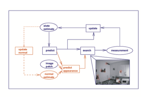
MonoSLAM
MonoSLAM: Real-Time Single Camera SLAM
Github
Andrew Davison, Imperial College London
Highlights
- First realtime running visual SLAM system
- Representative method in filter-based (a kind of backend method) visual SLAM algorithm.
Drawbacks
- The computational cost is large, where time complexity for each frame is $O(N^2)$ and $N$ is the number of mappoints. This is because EKF needs to update the covariance matrix as well. Therefore, map could only contains limited size of mappoint, thus reducing the robustness and geometric consistency.
- No loop closure detection and batch estimation. Is actually a VO instead of complete SLAM
Architecture
- Visual sensor type: monocular
- Initialization
- Observing a known object which could provide 4 known mappoint positions and known appearance
- e.g. a black grid could provide 4 corner as landmarks with known positions
- The initial pose of camera could be solved from the 3D-2D matches
- Observing a known object which could provide 4 known mappoint positions and known appearance
- Tracking and mapping are based on EKF (Extended Kalman Filter)
- Maintain a state vector of current camera state and several mappoint positions, with their covariance matrix
- Prediction step
- Use constant velocity, constant velocity to propagate the camera state and covariance matrix
- this assumes the accelerations occur in Gaussian distribution
- Use constant velocity, constant velocity to propagate the camera state and covariance matrix
- Update step
- Active search Shi-Tomasi based features for previous mappoints in new frame, get the matches
- Update the camera state and mappoint positions and their covariance matrix
- Other processing
- Initialize uninitialized mappoints
- Add new initialized mappoints to map, prune mappoints from map
- Use another EKFs to update the mappoints’ feature patch orientation
- No relocalization
- No loop closure detection
- Construct spare map
- Add new feature to map
- Feature initialization successfully
- The number of feature visible in current camera is less than a pre-defined threshold
- Delete old feature from map: the number of detection and matching attempts when the feature should be visible exceeds the pre-defined threshold
- Add new feature to map
Main EKF State
The main state vector consists of the current camera state and ~100 3D mappoints as following
- Camera state: 12 parameters, 6DoF pose, 3DoF velocity, 3DoF angular velocity
- Mappoings: 3DoF position
- Only contains initialized mappoints
Their are also other parameters existing in the map system, but those are not involved in the state vector, which will be updated by the main EKF.
Map System
- Feature content
- A feature is patch of image pixels around the Shi-Tomasi corner point
- For new feature detected in a frame, its mappoint will be initialized as
- Current camera position (3DoF)
- Direction vector (2DoF), from camera origin through feature position in imaging plane
- A unknown depth (1DoF), distributed uniformly
- It is assuming that feature patch lies in a 3D surface, so there is another 2DoF direction vector for the feature patch, which is initialized as the same direction of the mappoint’s direction vector above
- Feature search & match
- In the following camera frame, the feature patch will be projected into the new frame according to the mappoint’s position and feature patch direction, which result an ellipse in the new frame
- For uninitialized mappoint, since its depth is unknown, it will project to several ellipses in the new frame based on different values of the depth
- Mappoint Initialization
- As the following frames observe the uninitialized mappoint, its depth’s distribution will be updated based on the match score of different projected ellipses.
- When the depth’s distribution turns to a Gaussian like distribution, this mappoint is initialized successfully
- After a mappoint is initialized, it will be added to the main state vector as a 3D point, where
$$
p = p_c + d \cdot v
$$
The 3 dimensions also have their uncertainty, thus this mappoint will have an associated $3\times 3$ covariance matrix - The initialized mappoint could be illustrated as a 3D ellipsoid in space
- During the mappoint initialization, the direction vector won’t be updated. This is because the depth has larger uncertainty, and after the mappoint is added to the map, its 3D position will be updated as well.
- Feature patch direction initialization
- Fhe following camera frame, the 2DoF feature direction will be updated by EKF separately
- Each mappoint will have a separate EKF
PTAM
Parallel tracking and mapping
Github
Georg Klein, Oxford University
Highlights
- First to use multi-thread to separate tracking and mapping, introducing the concepts of frontend and backend, achieving realtime processing
- Majority of computation time complexity is in backend, while frontend tracking could run at very low lost
- First to introduce the concept of keyframes (frame with large disparity)
- Reduce the frequency of backend running, decreasing again the average computation time complexity for backend
- First to use BA (Bundle Adjustment, batch optimization) in backend, which has more accuracy than filter base methods and also saves computation resources
Drawbacks
Not very robust, limited environment size. Mainly used for indoor small workspace-related Augmented Reality applications
Architecture
- Visual sensor type: monocular, stereo
Initialization
- Requires user to take 2 images from 2 positions with smoothly translates (around 10cm)
- Extracts FAST points
- Five-point 2D-2D with RANSAC stereo initialization, following with BA
- Select points to hypothesis a plane with RANSAC
Tracking
- Initial pose from decaying motion model
- Project mappoints to the image, do patch search (epipolar search) for 50 mappoints, optimize pose with BA
- Reproject mappoints again, do patch search for 1000 mappoints, optimize pose again with BA
- Determine whether is keyframe based on several criterions. Insert keyframe into map
- Relocalization
- Suspend to send new keyframes to map when tracking is poor
- Tree-based feature classifier to find most similar keyframe when tracking is lost
- No loop closure detection
Optimization (Backend)
- Reproject mappoints to new keyframe to add more observations
- Triangulate mappoints from new keyframe and previous closest keyframe
- Local BA
- Closest 5 keyframes
- Mappoints observed by closest 5 keyframes
- Keyframes observing above mappoints (only provide constrains, not optimize)
- Refine data (observations, mappoints) during idle time by global BA
- Construct spare map
ORB SLAM
Paper:
  ORB-SLAM: a Versatile and Accurate Monocular SLAM System
  ORB-SLAM2: an Open-Source SLAM System for Monocular, Stereo and RGB-D Cameras
  ORB-SLAM3: An Accurate Open-Source Library for Visual, Visual-Inertial and Multi-Map SLAM
Github: Version 1, 2, 3
University of Zaragoza
Highlights
- Complete SLAM system, including tracking, mapping, relocalization, loop closure detection, global BA, supporting different visual sensors
- Propose to use ORB feature, Oriented Fast keypoints and Rotated BRIEF descriptors
- Follows PTAM’s multi-thread structure, achieved realtime processing, and adopts different techniques to enhance robustness, e.g.
- Covisibility graph for tracking, local BA, loop closing
- A survival of the fittest strategy for mappoints and keyframes
- Very robust, can operate in small and large, indoor and outdoor environments
- Usually used as baseline system
Drawbacks
- 3 thread structure requires more computation power, hard to work in embedded devices
- Sensitive to moving objects
Update
- ORB SLAM 2
- Add Stereo, RGBD sensor support
- ORB SLAM 3
- Add visual inertial sensor mode based on MAP estimation
- Add multiple map system to survive in long periods of poor visual environment
Architecture
- Visual sensor: monocular, stereo, and RGBD cameras
- Initialization (monocular): calculate Essential matrix and Homography matrix and selects the best
Tracking
- Extracts ORB features
- Compute initial pose by constant velocity motion model
- First pose estimation with last frame
- Update last frame’s pose based on its reference keyframe and create temporary mappoints
- Match temporary mappoints with key points from current frame
- Motion-only BA with matched mappoints
- Second pose estimation with local map
- Establish the temporary covisibility graph between current frame and previous keyframes
- Select mappoints observed by connected keyframes and the neighbors of connected keyframes
- Project selected mappoints to current frame, do the feature matching
- Perform motion-only BA with matched mappoints
- Determine whether current frame is a keyframe based on the covisibility graph
- Relocalization
- Converts the frame into bag of words and queries the recognition database to find most similar keyframe
- Computes camera pose using the PnP algorithm.
Loop closure detection
- Compute a minimum BoW score from current keyframe and neighbors in the covisibility graph
- Select candidates of loop frame whose 3 consistent frames are larger than the minimum score
- Compute the Similarity transformation between current keyframe and candidates of loop frame using 3D-3D methods with RANSAC, select loop frame based on inliers
- Update the pose of current frame and neighbor frames according to the similarity transformation and the the loop frame pose
- Reproject mappoints of loop frame and its neighbors to current frame and its neighbors. Fuse the mappoints
- Do the pose graph optimization based on the Essential graph
- Start a new thread for global BA with all keyframes and mappoints
Optimization (Backend)
- Update the covisibility graph and spanning tree
- Cull recent mappoints
- Create new mappoints by triangulation
- Local BA
- Current keyframe and connected keyframes in covisibility graph
- Mappoints observed by above keyframes
- Keyframes observing above mappoints (only provide constrains, not optimize)
- Cull keyframes
Concepts
- Covisibility Graph
- An undirected weighted graph, where each node is a keyframe and an edge between two keyframes exists if they share observations of the same map points (at least 15), the weight the edge is the number of common map points
- Used for frontend pose estimation, new keyframe decision, backend scale
- Essential Graph
- A spanning tree from the initial keyframe, which provides a connected subgraph of the covisibility graph with minimal number of edges. When a new keyframe is inserted, it is included in the tree linked to the keyframe which shares most point observations.
Tricks of Project
- Use
associate_with_groundtruth.txtas the input, rather thanassociate.txt - Local map consists of mappoints observed by current frame and connected keyframes (using covisibility graph) and their connected keyframes
- Insert keyframe and mappoints loosely, but cull them strictly
Direct Method
DTAM
DTAM: Dense Tracking and Mapping in Real-Time
Github
Richard A. Newcombe, Imperial College London
Highlights
Dense Tracking and Mapping uses direct method for tracking and it could construct dense map.
Architecture
- Visual sensor type: stereo
- Initialization: stereo measurement to reconstruct initial map
- Tracking
- Pose estimated by synthetic view generation from the reconstructed map
- Represent the mappoints with inverse depth
- Maintain the depth map of reference frame
- Relocalization: tree-based feature classifier to find most similar keyframe
- No loop closure detection
- Backend
- Triangulation for mappoints based on multi-baseline stereo
- Mappoints are optimized based on space continuity
- Construct dense map
LSD SLAM
Paper:
  LSD-SLAM: Large-Scale Direct Monocular SLAM
  Semi-Dense Visual Odometry for AR on a Smartphone
Github
TUM
Highlights
- A leading SLAM system based on direct methods
- Support to build consistent, large-scale map
- Map is semi-dense because only pixels with large intensity gradient are tracked
- Sensitive to camera intrinsic and camera exposure, and fast motion
- Depend on feature based method to detect loop closure
Architecture
- Visual sensor type: monocular, stereo
- Initialization: initialize first keyframe with a random depth map and large variance
Tracking
- Tracking of new frames
- Use pose of previous frame as initialization
- Estimate pose with respect to current keyframe by minimizing variance-normalized photometric error
- Solve by iteratively re-weighted Gauss-Newton optimization
- Depth map estimation
- Frame is keyframe: camera moves too far away from existing map
- Projecting points from previous keyframe to new keyframe, to initialize map
- One iteration of spatial regularization and remove outliers
- Replace previous keyframe
- Frame is non-keyframe
- Perform small-baseline stereo comparisons for image regions where expected stereo accuracy is large
- Use filtering approach to refine previous depth map
- Frame is keyframe: camera moves too far away from existing map
- Maintain the image, inverse depth image, and variance of inverse depth of each frame
- Tracking of new frames
- Relocalization
- Loop closure detection: use feature-based method to detect
- Optimization (Backend)
- Triggered when a keyframe is replaced by new keyframe, which means its depth map will not be refined further
- Map is represented as a pose graph of keyframes
- Pose Graph optimization is performed
- The depth map of each keyframe is scaled such that the mean inverse depth is one
- When performing keyframe-to-keyframe alignment, a direct method is used on sim(3). Error function consists of photometric residual and scale residual.
- Construct semi-dense map (limited to high-intensity gradient areas)
Mobile AR Application
- Tracking based on direct image alignment
- Mapping based on pixel-wise filtering over many small-baseline stereo comparisons
- Real-time (above 30 Hz) processing in mobile phone
- Lower the image resolution to $160 \times 120$
- Use NEON instructions to operate 4 pixels at the same time
- Generate collision mesh from semi-dense depth map
- Estimate the depth of pixels without a depth hypothesis
- Generate triangle mesh from the depth map by interpreting the depth pixels as corners of a regular triangle grid
- Use IMU to get the direction of gravity, then help to determine plane
DSO
Highlights
- Combines a fully direct probabilistic model (minimizing a photometric error) with consistent, joint optimization of all model parameters (geometry - inverse depth, and camera motion)
- Could build sparse map across regions that have intensity gradient
- Sensitive to camera exposure
Architecture
- Visual sensor type: Monocular, Stereo
- Initialization: Initialize first keyframe with a random depth map and large variance
Tracking
- Initial pose by constant motion model of last frame
- Estimate pose by conventional two-frame direct image alignment (project active points into current frame)
- Keyframe determination
- Mean square optical flow, for measuring field of view changes
- Mean flow without rotation, for measuring camera occlusions and disocclusions
- Relative brightness factor between 2 frames, for measuring camera exposure time changes
- If not keyframe
- Update the depth of previous immature points (point without depth estimated) by minimizing the photometric error
- If keyframe
- Generates new immature points
- Well-distributed in the image
- Have sufficiently high image gradient magnitude with respect to immediate surroundings
- Insert it to sliding window (backend)
- Generates new immature points
- No relocalization
- No loop closure detection
Optimization (Backend)
- Maintains a sliding window containing active keyframes and mappoints. Triggered by new keyframe insertion
- Marginalization old keyframes
- Marginalization determination
- Latest 2 keyframes are always kept
- Frames with less points visible in new keyframe is marginalized
- If exceeds the sliding window, marginalize the keyframe maximizing a “distance score” to keep more keyframes close to the new keyframe
- Remove related mappoints to keep the sparsity pattern of Hessian matrix
- Mappoints observed by old keyframe but not by new keyframe are marginalized
- Mappoints observed by old keyframe and new keyframe are dropped (this is suboptimal, but it could keep the optimization calculation fast)
- Marginalize old keyframe(s) using Schur complement
- Marginalization determination
- Project mappoints already in sliding window to new keyframe to produce the residual
- Add Mappoints
- Project new mappoints candidates (already have depth initial guess from frontend, but not in sliding window) to current keyframe
- Selects those maximizing the distance to existing point to add to the sliding window
- Produce the residual
- Bundle Adjustment on photometric error
- Each error term is defined by 2 keyframes’ pose, depth of mappoint, and photometric parameters
- Require derivate of error function on pose of camera (6 DOF), depth of mappoints, and 2 parameters related to photometric. 9 elements in total
- Remove outliers
- Construct sparse map
Mappoint Representation
Different like feature-based method like ORB SLAM using $[x, y, z]$ to represent the position of a mappoint, DSO uses the inverse of depth, and its host frame to represent a mappoint.
$[x, y, z]$ form means the mappoint is a point whose projection in image generates a maximum in the used corner response function, while in DSO, the mappoint is the point where the source pixel’s ray hits the surface, thus there is only 1 dimension unknown, its depth. And use the inverse of depth could suit the Gaussian framework more, and could represent point in far-away.
Since the point only have 1 depth dimension, the observation error term requires current frame and the host frame of the mappoint to construct – using the host frame’s pose, the pixel coordinate in the host frame, and the inverse of depth could compute the projected position of the mappoint in the current frame.
SVO
Paper:
  SVO: Fast Semi-Direct Monocular Visual Odometry
  SVO: Semi-Direct Visual Odometry for Monocular and Multi-Camera Systems
Github: Version 1, 2
ETH Zurich
Highlights
- Uses feature-based method to initialize mappoints
- Uses direct methods to build corresponding relationship of image patches between frames, saving the time to calculate descriptors and perform feature matching
- Since it still requires to extract keypoints, so called “Semi” direct method
- Used on MAVs so assuming some planar scenes
- Not very good performance in held camera scenario
Update
SVO 2: Add multi-camera systems
Architecture
- Visual sensor type: Monocular
- Initialization
- extract FAST keypoints
- assume planar scene, compute Homography matrix
- triangulate feature points from first two keyframes
Tracking
- Pose initialization through sparse model-based image alignment
- direct methods between current frame and previous frame
- minimizes the photometric error of all patches ($4\times 4$ pixels around feature point)
- Relaxation through feature alignment
- project all visible 3d points to current frame
- Lucas-Kanade algorithm for current frame and keyframes in map
- Pose and structure refinement
- Motion-only BA to minimize geometric error with previous keyframes in map
- Pose initialization through sparse model-based image alignment
- Relocalization: project mappoints to current frame assuming pose of current frame is same with previous frame
- No loop closure detection
Optimization (backend)
- Probabilistic depth-filter
- depth of 2d features for which the corresponding 3d points is not known at the beginning
- depth estimation of a feature is modeled with a probability distribution
- new observation is used to update the distribution in a Bayesian framework
- variance of depth distribution becomes small enough
- 3d point creation, add to map, and used in motion estimation
- Sliding window to keep keyframes in the map
- Probabilistic depth-filter
- Construct sparse map
Summary
from Visual SLAM algorithms: a survey from 2010 to 2016
| Algorithm | Frontend | Map density | Loop Closure | Global Optimization | SLAM vs VO |
|---|---|---|---|---|---|
| MonoSLAM | Feature | Sparse | No | No | VO |
| PTAM | Feature | Sparse | No | Yes | SLAM |
| ORB SLAM | Feature | Sparse | Yes | Yes | SLAM |
| DTAM | Direct | Dense | No | No | VO |
| LSD SLAM | Direct | Semi-dense | Yes | Yes | SLAM |
| DSO | Direct | Sparse | No | No | VO |
| SVO | Semi-Direct | Sparse | No | No | VO |
Note. MonoSLAM is using EKF, so no concepts of frontend and backend. All other methods’ backend use batch optimization.
Personal System
VO for RGBD camera, link
- Frontend
- Set initial value with constant model
- 3D-2D P3P with RANSAC to estimate initial value of pose
- using ORB features
- 3D-2D BA to estimate the final pose
- No Relocalization
- No loop closure detection
- Backend
- Triangulation for mapppoints based on different keyframes
- BA based on Covisibility Graph
- Construct sparse map
VO for Stereo camera, link
- Frontend
- GFTT key-points
- Optical flow for matching
- Estimate initial value of frame based on last 2 frames’ pose changes
- 3D-2D BA to estimate the final pose
- No Relocalization
- Loop closure detection (pending)
- Bag-of-words image retrieval technique
- Backend
- Triangulation for mappoints based on different keyframes
- Local BA with sliding window for the latest 7 key-frames’ poses and corresponding mappoints
- Construct spare map
Reference
- Taketomi, T., Uchiyama, H., & Ikeda, S. (2017). Visual SLAM algorithms: a survey from 2010 to 2016. IPSJ Transactions on Computer Vision and Applications, 9(1), 1-11.
- https://www.quora.com/What-is-the-difference-between-loop-closing-and-relocalization-in-visual-slam
- Mur-Artal, R., Montiel, J. M. M., & Tardos, J. D. (2015). ORB-SLAM: a versatile and accurate monocular SLAM system. IEEE transactions on robotics, 31(5), 1147-1163.
- Mur-Artal, R., & Tardós, J. D. (2017). Orb-slam2: An open-source slam system for monocular, stereo, and rgb-d cameras. IEEE Transactions on Robotics, 33(5), 1255-1262.
- Campos, C., Elvira, R., Rodríguez, J. J. G., Montiel, J. M., & Tardós, J. D. (2020). ORB-SLAM3: An accurate open-source library for visual, visual-inertial and multi-map SLAM. arXiv preprint arXiv:2007.11898.